Problem
The system is experiencing Position Errors and/or Over Current faults when you attempt to connect to you new system that was tested and tuned at the factory.
Solution
Position Error and Over Current faults are common for new systems to experience. They are the two most common errors customers receive primarily because of how customers receive the errors.
Do be aware that Position Error faults and Over Current faults go hand-in-hand. If the instructions under the Position Error section do not help, see if suggestions in the Over Current section will help. And if the instructions under the Over Current section do not help, see if suggestions in the Position Error section will help
Position Error & Over Current Faults
Position Error faults are a result of the difference between the Position Command and Position Feedback being too large. Ultimately this difference is determined by the PositionErrorThreshold parameter.
Over Current faults are a result of the motor drawing an RMS current higher than the value specified in the AverageCurrentThreshold parameter.
With just looking at your system, visually, anything that seems like it could be causing something like this to happen is worth investigating, even if it is not something we list below.
With that in mind, here are some situations and things to keep an eye out for.......
Shipping clamps and other External Devices
Before starting up your system and attempting to move, you should ensure that all external devices are safe from collision.
You should also ensure that all shipping clamps have been removed from the system. Aerotech uses Red aluminum brackets for our shipping clamps.
Any system that uses direct-drive motors should be able to move freely by hand with very little effort. Direct-drive motors are motors that do not use mechanics (ex. ballscrews, worm gears, etc.) to move the system.
Solution:
- Ensure all external devices are free from collision with the systems range of travel.
- Ensure all shipping clamps have been removed.
If you are unsure if you motor uses direct drive motors do not attempt to force movement by hand without consulting Aerotech. Doing so could cause further damage.
Hardware and Parameter Configuration
Common causes of Position Error faults are improper parameter or hardware configuration.
Parameters:
If the system was purchased and tested as a system by Aerotech (TAS, Test As System), then Aerotech would have provided a parameter file (A3200: *.prma, Ensemble: *.prme, or Soloist: *.prms) or a Machine Controller Definition file (Automation1: *.mcd). The parameter file or MCD contains all of the proper motor and encoder setup for your system. Ensure that you are using the correct parameter file/MCD for your system. For non-configured systems you will need to refer to the Getting Started section of the Help file for configuring parameters; for Automation1, instead refer to the Machine Setup documentation.
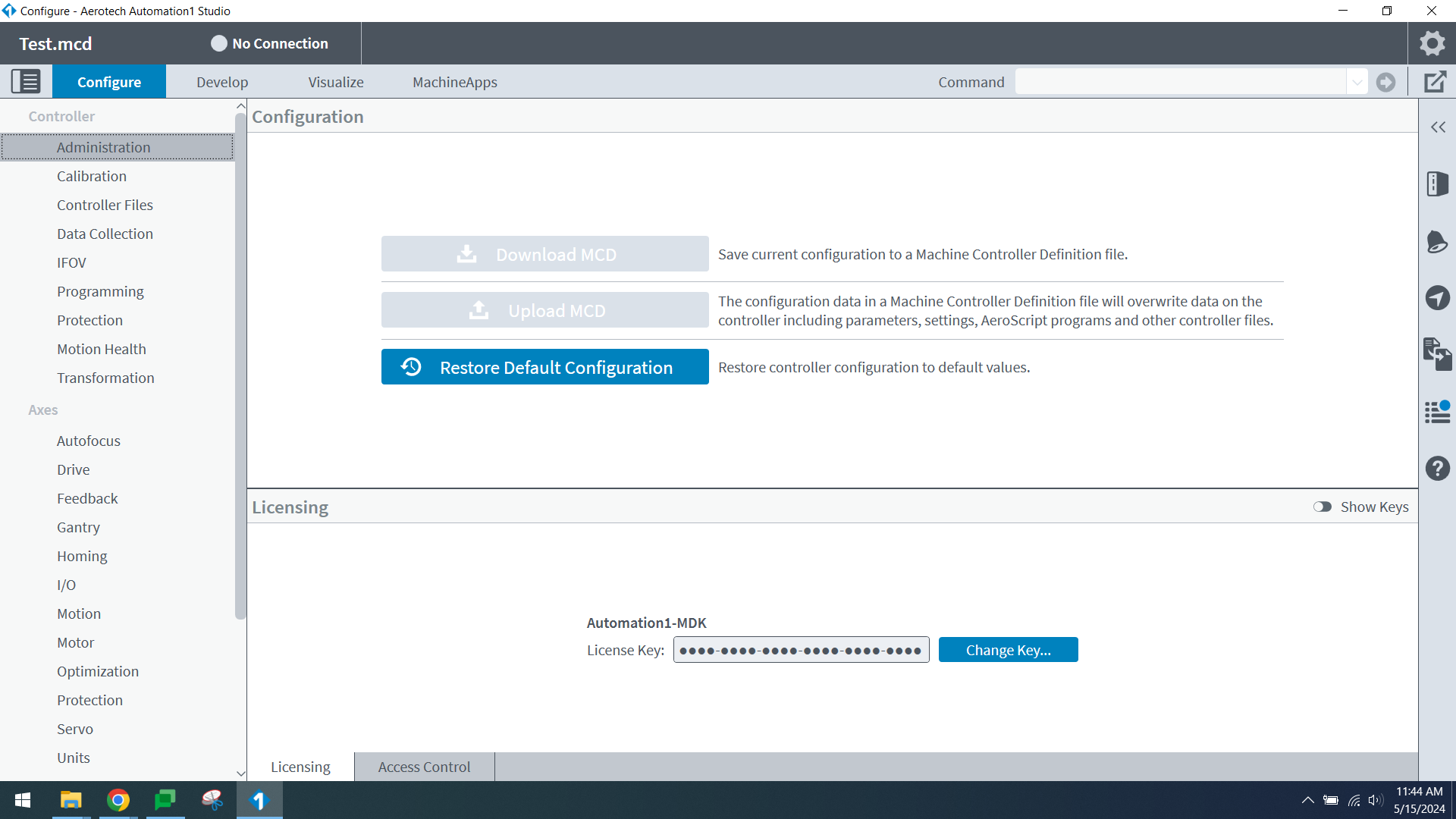
- If using Automation1: Ensure that the correct MCD has been uploaded to the controller in Automation1 Studio, Configure tab.
This is done by clicking "Upload MCD" under Controller > Administration. You must be connected to a real controller or to an -iSMC installation to do so.
- If using A3200: Ensure that the correct parameter file is set as the Active Parameter file in the Configuration Manager.
This is done by right-clicking the parameter and selecting "Use as Active Parameters".

- If using Ensemble or Soloist: Ensure that the correct parameter file is being send/committed to the controller.
This is done by clicking-and-dragging the *.prme/*.prms file from the Open Files to the Ensemble Controller.

Hardware:
As far as hardware is concerned, if this was a TAS configured system you should have received a System Interconnect drawing. This drawing details how you should connect your system. What cables to use, where to connect them and what types of amplifiers to connect them to.
If you have a system that has two identical(or similar) stages in an XY configuration setup, verify that you are connecting the axes to the correct controllers and that you are connecting them in the right order. It is very easy to get the top and bottom axes swapped by accident.
Solution:
- Ensure that you are using the proper parameter file
- Ensure that you have the proper hardware configuration.
Payload and Tuning
In systems where Aerotech tests the stages as a system before shipping we attempt to mimic our customer's payloads. But our recreation of your payload may not always be exact. If your stages were tested as a configured system you should have received a System Specification sheet. Please verify that your current payload is similar to that of the payload mass listed on the specification sheet.
If we configured and tuned the system for 10kg, but your are using 50kg, there may not be enough power coming from the PID loop to move your 50kg payload. In this situation the solution it to either remove the excess weight or retune the system.
Alternatively, payloads that are awkwardly shaped or different from the payload tests at Aerotech could also cause instability in the system causing the Position Error Fault.
Solution:
- Re-tune. If you are in software version 5.03 or later you will have access to the EasyTune feature in the Digital Scope application. This can be used to re-tune your system for the proper payload
- If you do not have EasyTune then you will need to use either AutoTune or Manual Tuning through Loop Transmission (Bode plots).
- Ensure that your payload approximately matches that of the payload listed on the System Specification Sheet.
No motor power? No holding torque?
No motor power or no holding torque is a common reason for Position Error faults. The system will attempt to enable, however, if there is no power going to motor then the stage will not move and will trigger a Position Error fault.
Solution:
- Verify that the appropriate Motor Power is being sent to the controller. For the specific input location on your controller please refer to the controller hardware manual.
- If you are using an Npaq controller, try swapping the Amplifier card (ex. DP32030E) with an identical amplifier card from the front of the Npaq.
Fault on Enable? Odd jerking motion on Enable?
Odd movement when you enable or shortly after enabling can be a result of improper motor phasing (motor phases A, B, and C). You may also notice this as a quick jerking motion.
The cause of this may be due to improper motor phasing. This could be because of a hardware problem with the motor or just that you have the motor phases going into the controller swapped. If using a configured system, verify that the correct hardware connections are being used as mentioned in the Hardware and Parameter Configuration section above. If not using a configured system, please verify this through the Controller and Stage hardware manuals.
One additional test to try would be to measure the phase-to-phase resistance values of the Motor Output leads and the Motor Output connector on the controller. Resistances between the phases(A-B, A-C, and B-C) should be similar to each other, if they are not then that could indicate a short. All resistances from the phases to ground(A-GND, B-GND, C-GND) should be open circuits (very high or infinite resistance).
Solution:
- Verify correct hardware connections, specifically the motor phases A, B, and C
- Measure phase-to-phase resistances to verify motor hardware functionality.
Humming/Oscillating noises
These noises are caused by improper servo loop tuning, and go hand-in-hand with Over Current faults. In systems where Aerotech tests the stages as a system before shipping we attempt to mimic our customer's payloads. But our recreation of your payload may not always be exact. If your stages were tested as a configured system you should have received a System Specification sheet. Please verify that your current payload is similar to that of the payload mass listed on the specification sheet.
Servo Tuning is dependent on the size and weight of the payload being used. If Aerotech tested and tuned the system with 50kg, and you only have 10kg, this will cause the PID loop to try and overcompensate, causing Humming/Oscillating noises.
Solution:
- Re-tune. If you are in software version 5.03 or later you will have access to the EasyTune feature in the Digital Scope application. This can be used to re-tune your system for the proper payload
- If EasyTune is not available the recommendation is to lower the servo loop gains by %20. These include GainKi, GainKp, and GainKpos in the parameter file.
- Test the system again. If the noise is still present, decrease the gains by another %10-15. Continue doing this until the noise goes away
- Ensure that your payload approximately matches that of the payload listed on the System Specification Sheet.
In rare cases where tuning or lowering gains does not help, please refer to the Hardware and Parameter Configuration section. There may be something wrong with your parameter file configuration.
If the Hardware and Parameter Configuration section does not help, contact Aerotech Global Technical Support. There may be a hardware problem with the system.
Z-axis mechanical Brake?
Many Z-axis stages use mechanical brakes to prevent the axis from slipping downwards when it is not being used.
This same mechanism could also be the reason why the position error could increase or the RMS current increase, because it is physically locked in place when it is trying to move.
The system should be configured to disable the brake when you enable the axis to allow it to move. Verify that you have the EnableBrakeControl parameter set to enable the brake.
Some controllers also require the user to externally power the brake via the Brake Input pins with a 24VDC supply. Verify this by checking your controller hardware manual for the pin locations and the necessary voltage supplies.
Solution:
- Verify that your brake is being powered properly
- Verify that you parameters are configured to use a mechanical brake
Most Aerotech designed brakes will be integrated into the systems. If this is a configured TAS system then the parameters and how to connect the cables should be provided in the System Interconnect drawing you received. If this is not a configured TAS system then consult Aerotech Global Technical Support or your stage and Controller hardware manuals for proper configuration.
Related articles
-
Page:
-
Page:
-
Page:
-
Page:
-
Page: