This procedure is an example of how to set up a Modbus Client connection in Automation1 2.5.0 using a WAGO I/O controller as the Modbus Server.
Test Equipment
- A PC with at least one Ethernet port.
- This port (or entire Ethernet card) will be used only for Modbus and cannot be used for any other purpose (such as Internet access). Two or more Ethernet cards can be installed in the same PC, but one must be dedicated for real-time use with Modbus.
- WAGO Ethernet Settings software (see below for installation instructions)
- WAGO I/O Controller (IO-WAGO-750-842 in this case)
- End module (IO-WAGO-750-600)
- +24VDC Power Supply
Procedure
- The WAGO controller can have multiple input/output, analog/digital modules connected to it. At a minimum, the end module (IO-WAGO-750-600) must be connected to the WAGO controller.
- Connect a +24VDC power supply to WAGO controller
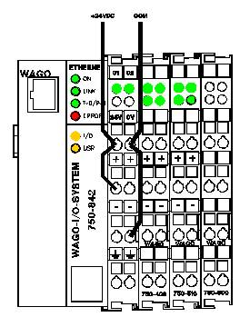
- Connect the WAGO controller to a dedicated Ethernet card or Ethernet port on the PC
- This will require the WAGO Ethernet Settings software, proprietary USB cable from WAGO, and WAGO USB driver.
- Refer to the following video to assign an IP address to the WAGO controller: Assign IP address of the PFC with Ethernet Settings
The IP address and Subnet Mask must be on the same network as the PC Ethernet card or Ethernet port the WAGO is connected to. If you are unsure what IP address and Subnet Mask to use, see Setting IP Addresses, Subnet Masks, and Gateways.
A standard network setting for example might be:
WAGO Controller:
IP Address: 198.162.1.22
Subnet Mask: 255.255.0.0
Default Gateway: 0.0.0.0
PC Ethernet adapter:
IP Address: 192.168.1.23
Subnet Mask: 255.255.0.0
Default Gateway: 0.0.0.0
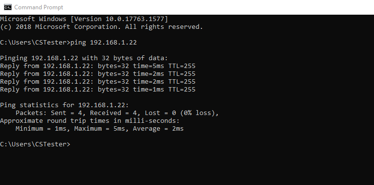
- (Optional) Once the WAGO and PC network settings have been configured, ping the WAGO from the PC to ensure that communication is successful.
- Open Command Prompt
- Type ping <IP Address of the WAGO>
- The WAGO controller will respond as follows:
- Open an Internet browser
- Navigate to the IP address that is configured for the WAGO. This will open the WAGO-I/O-System page as shown below.
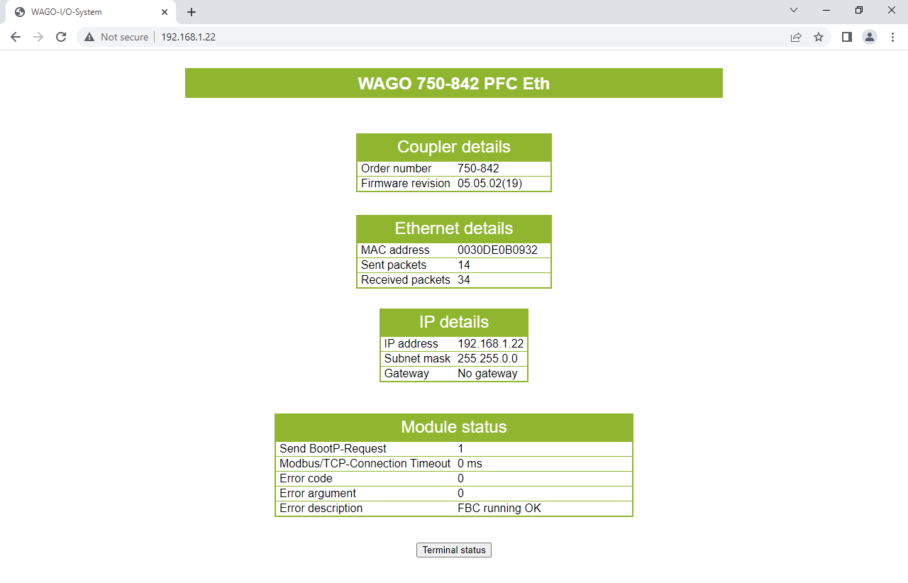
- Click on Terminal Status at the bottom of the page. This will open the Terminal Status page as shown below.

- The Terminals info section shows each module connected to the WAGO controller. In the example above, we have:
- WAGO 750-459 - 4 channel analog input module
- WAGO 750-402 - 4 channel digital input module
- (x3) WAGO 750-504 - 4 channel digital output module
- WAGO 750-459 - 4 channel analog input module
- The Process image section shows the total number of I/O connected to the WAGO controller. In the example above, we have:
- 12 digital outputs
- 4 digital inputs
- 8 analog inputs
- Record this information as this will be needed to generate Modbus mappings
For Windows 10:
Open Device Manager and expand "Network adapters"
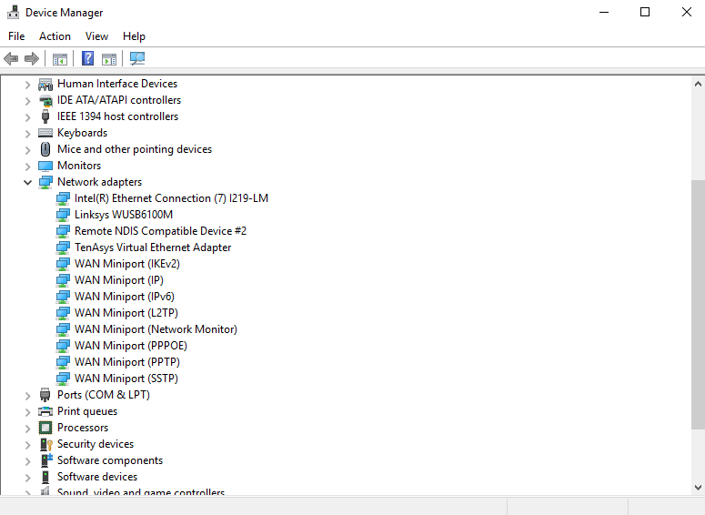
Right click on the adapter that you wish to use for Modbus and select "Properties"

If you are unsure which Ethernet adapter to select:
Open Control Panel and click on "Network and Sharing Center"
- Click on "Change adapter settings"
- Disconnect or reconnect the WAGO to the Ethernet port on the PC. Note which one of the adapters changes its network status.
On the "Details" tab, select "Hardware Ids" from the dropdown
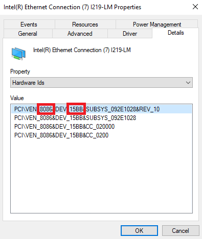
Record the 4 digit VEN and DEV numbers.
Compare this to the list of compatible network interface cards on the Modbus TCP IP Overview page.

- If the card is listed, note the section under which it is listed (Intel Gigabit, Realtek Gigabit, Realtek 10/100 Mbps, etc.). This is the device driver for the Ethernet card.
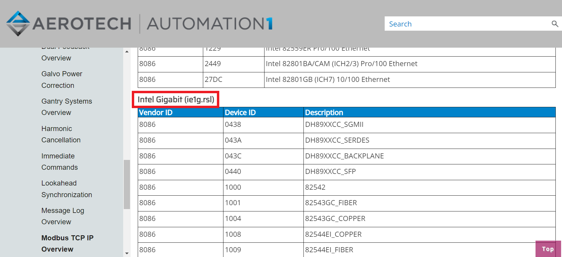
- If the card is not listed, it is not compatible for use with Modbus in Automation1.
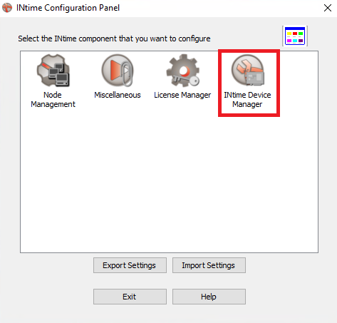
- Open INtime Device Manager (Start > All Programs > INtime > INtime Configuration). Then double click to open "INtime Device Manager".
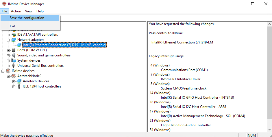
- In the Windows devices tree, find your network adapter. Right-click your adapter and select "Pass to INtime using MSI"

- Click "File" and then "Save the Configuration". The card will now be listed under the INtime devices tree.
- Close INtime Device Manager and restart the PC
- Open INtime Device Manager (Start > All Programs > INtime > INtime Configuration). Then double click to open "INtime Device Manager".
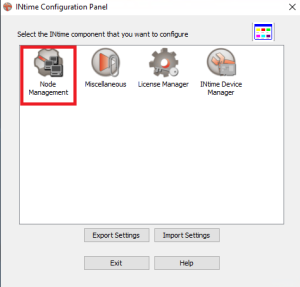
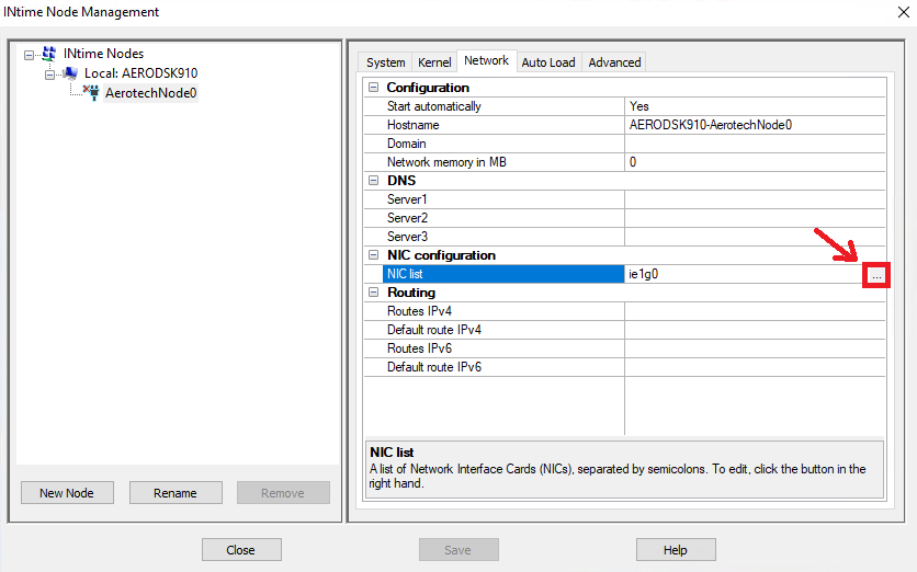
- Open INtime Node Management (Start > All Programs > INtime > INtime Configuration). Then double click on "INtime Node Management".
- Select the "Network" tab
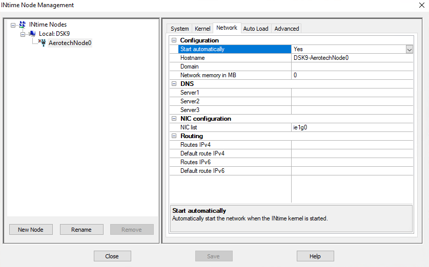
- Confirm that the "Configuration > Start Automatically" is configured as "Yes" to make sure the network stack is opened automatically.
- To add a new NIC configuration to the list, click the three small dots in the right corner of the "NIC Configuration > NIC list" field.
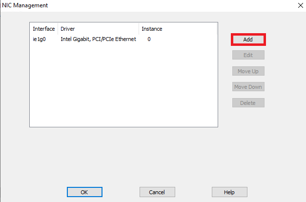
- Select "Add" to configure the NIC
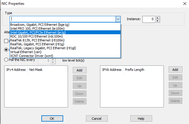
- Use the "Type" dropdown to configure the corresponding device driver (see Step 1 to determine the correct device driver).
- Configure the network card using a static network configuration.
- Click "Add" to configure an IPv4 address. Automation1 currently supports IPv4 at the application layer.
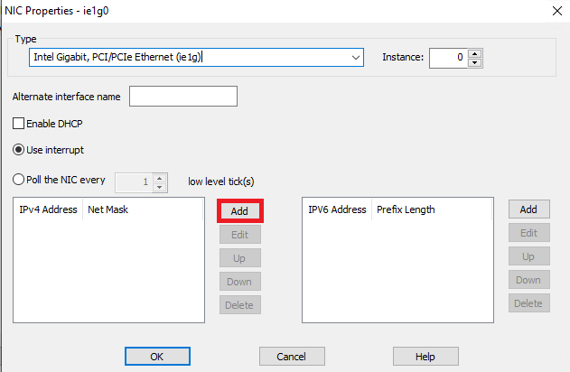
- Use the dialog to configure the IPv4 Address and Net Mask.

- Click "OK" to apply the new IP networking configuration.
- Click "Save" to save the networking configuration
- Close INtime Node Management and restart the PC
- Click "Add" to configure an IPv4 address. Automation1 currently supports IPv4 at the application layer.
- Use the "Type" dropdown to configure the corresponding device driver (see Step 1 to determine the correct device driver).
- (Optional) Ping the WAGO under real-time control to verify communication
- Open Automation1 Studio. Connect and Start the controller.
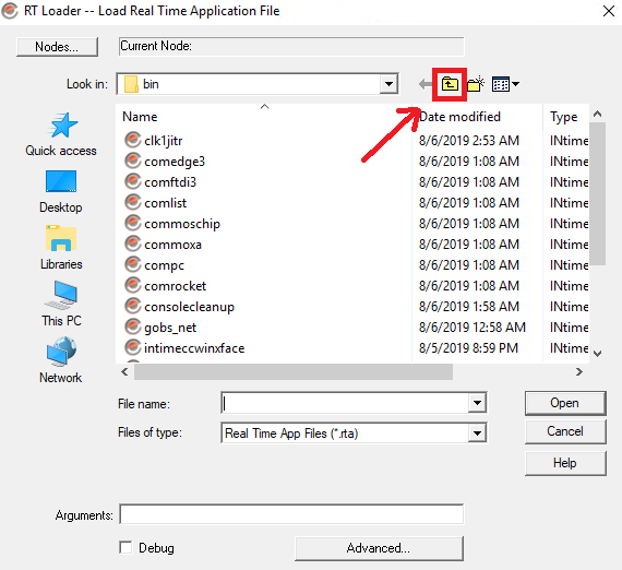
- Open RT Application Loader (Start > All Programs > INtime > RT Application Loader)
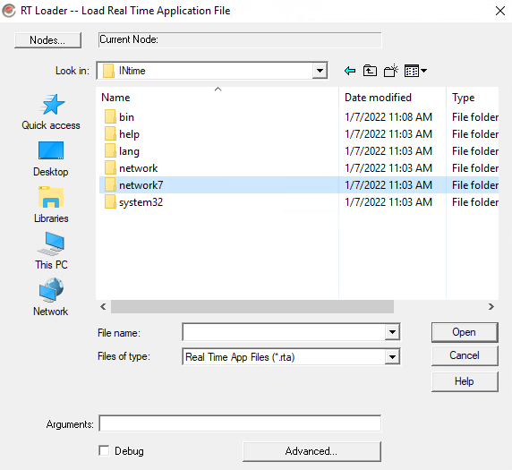
- Navigate one level up to the network7 folder
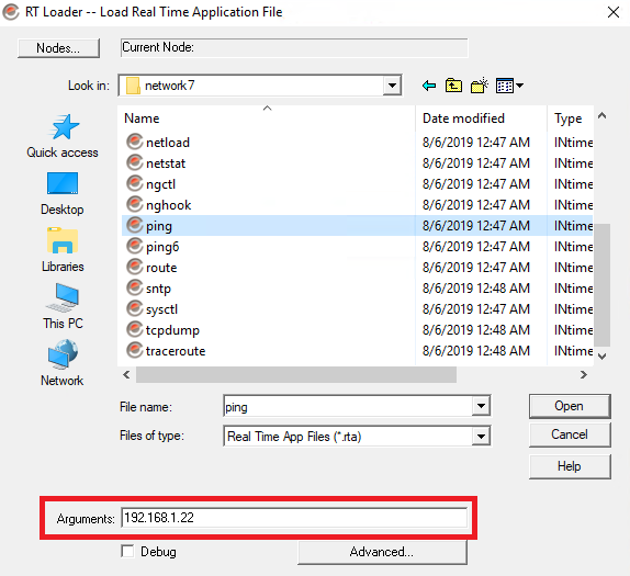
- Select ping.rta in the network7 folder and enter the IP address of the WAGO in the Arguments field
- Click Open. A command prompt window will open and ping the IP address of the WAGO. This will look like:
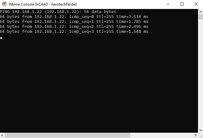
- Use CTRL-C to stop the ping operation.
- Open INtime Node Management (Start > All Programs > INtime > INtime Configuration). Then double click on "INtime Node Management".
- Open Automation1 Studio
- Navigate to the Develop workspace
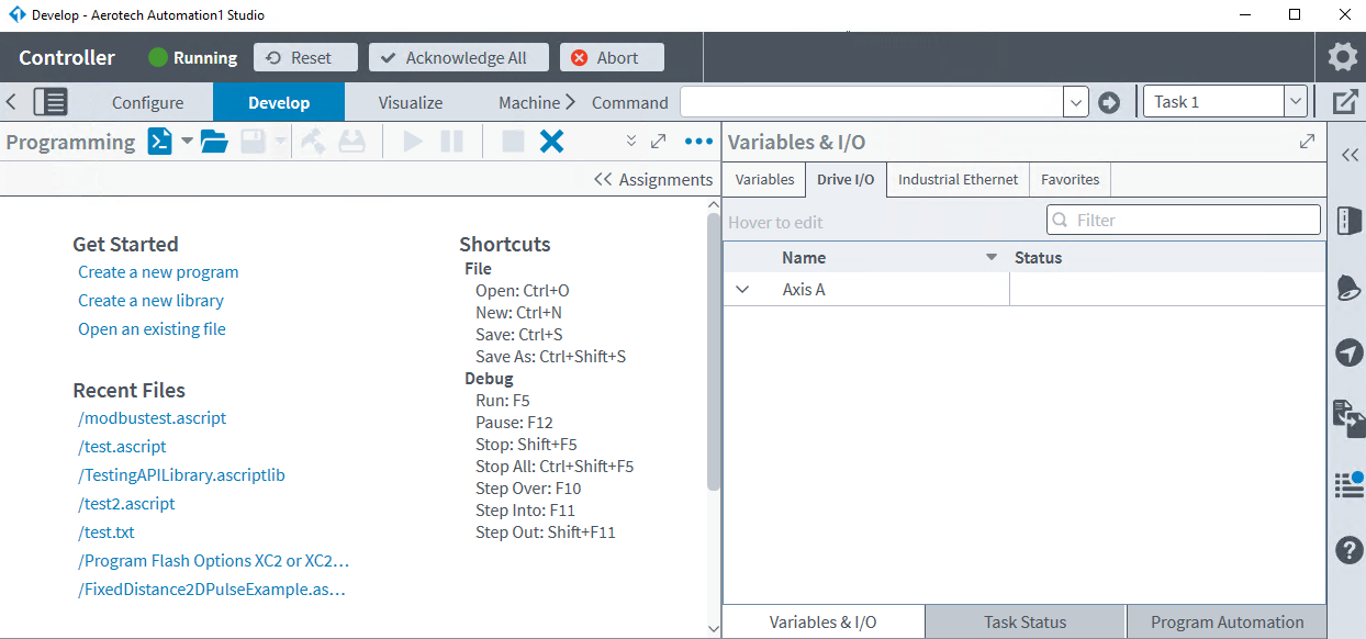
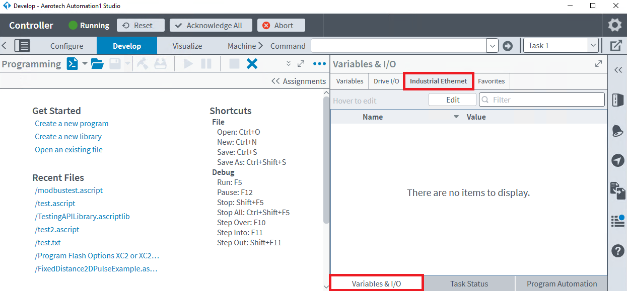
- On the Variables & I/O tab, select Industrial Ethernet
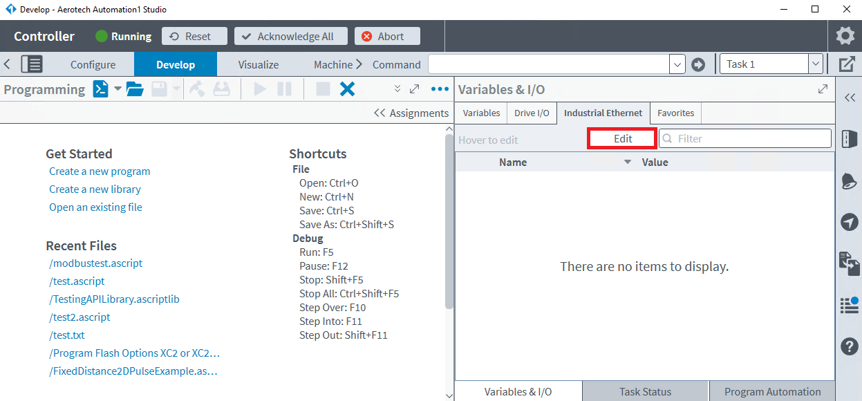
- Click Edit and select Yes to the prompt that appears about resetting the controller.
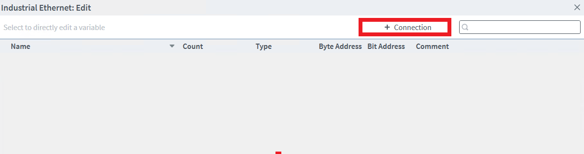
- Create an Industrial Ethernet connection
- Enter the connection details
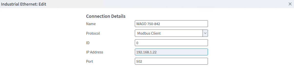
- Name: The name of the connection. This name is informational only and is used to differentiate between Modbus Client connections within Automation1.
- Protocol: Modbus Client connection as the WAGO will act as the Modbus Server (slave device) in this example.
- ID: The Unit ID of the Modbus Client being connected to. This value is used by the Modbus protocol to differentiate between multiple Modbus Clients operating at the same IP address.
- IP Address: The IP address of the Modbus Client being connected to.
- Port: The port of the Modbus Client being connected to. The TCP/IP stack of Modbus connects over port 502.
- Click Add to add the connection
- Expand the new connection.
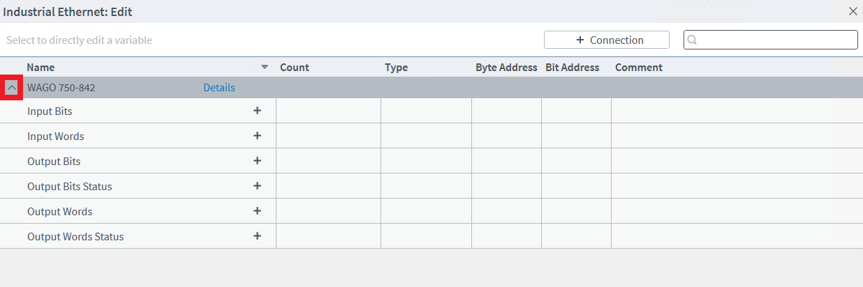
- On the WAGO, the I/O modules map to the Modbus registers as follows:
- OutputBits = Digital outputs
- InputBits = Digital inputs
- InputWords = Analog inputs
- OutputWords = Analog outputs
- Recall that this particular WAGO has the following modules, in order:
- WAGO 750-459 - 4 channel analog input module
- WAGO 750-402 - 4 channel digital input module
- (x3) WAGO 750-504 - 4 channel digital output module
- WAGO 750-459 - 4 channel analog input module
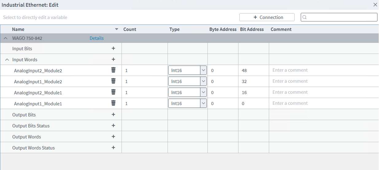
- To map the Analog Inputs, add an Input Words connection for each Analog Input available (4 in this example). Each Analog Input takes 16 bits. The WAGO unit automatically applies byte offsets so everything can be specified from byte 0.
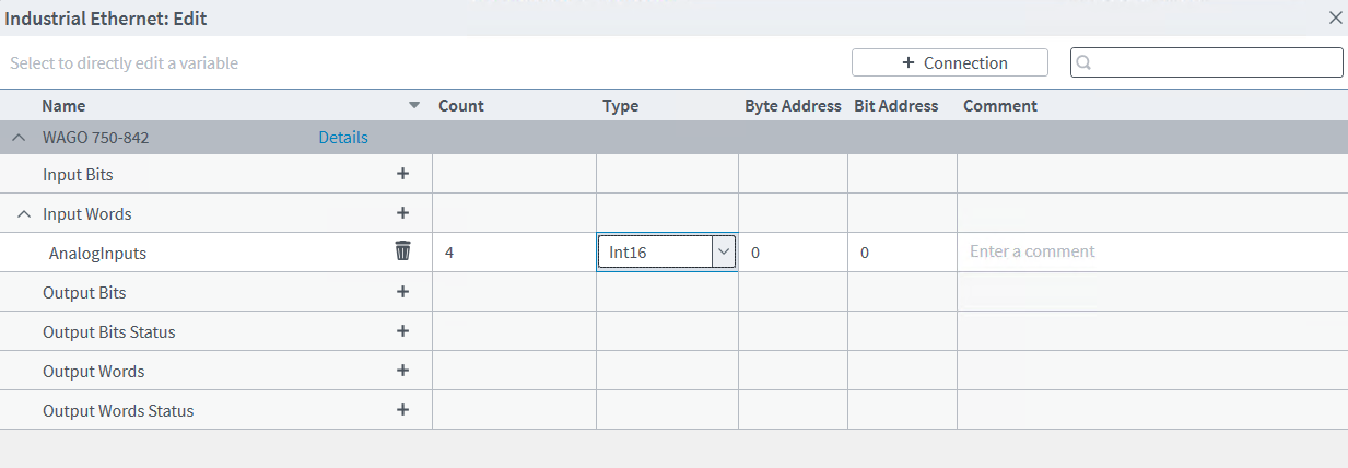
- Alternatively, changing the Count to 4 will specify an array starting at byte 0 instead of separate variables:
- Add the Digital Inputs as InputBits and the Digital Outputs as OutputBits respectively. Each digital input or output takes 1 bit.
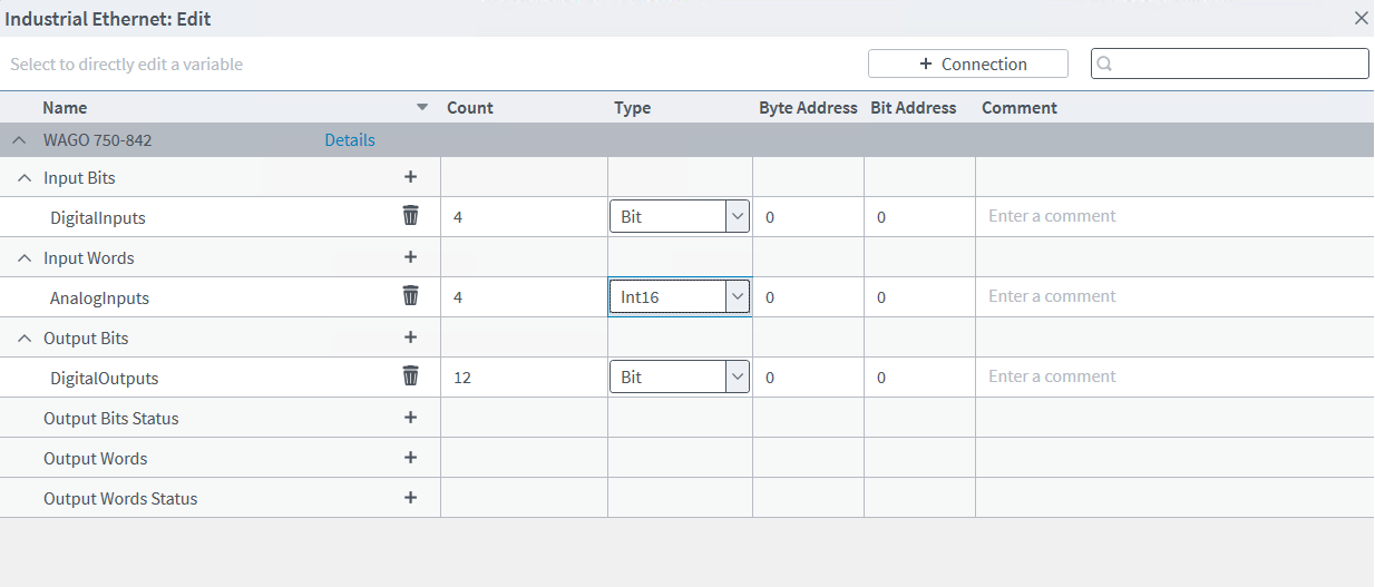
- Click Save to apply the configuration.
- Expand the new connection.
- Create a new AeroScript program in the Develop tab of Automation1 Studio.
- The Modbus I/O can be accessed using the following AeroScript syntax:
- $<variableName>
- $<variableName>[bit]
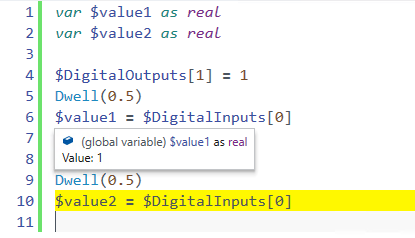
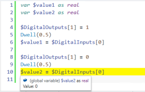
- For example, using the WAGO 750-842 in this example:
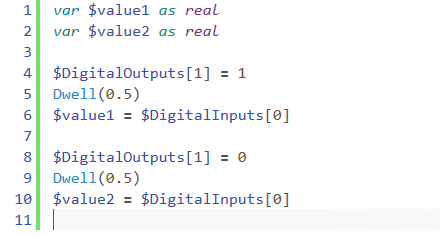
- This example sets the second Digital Output on the first Digital Output module to 1, then reads the value of the first Digital Input on the Digital Input module. I have wired this output and input together so the AeroScript variables should update accordingly, as shown below: