This guide is intended for analog/sine encoder stages that are experiencing a Position Feedback Fault, Velocity Feedback Fault, for maintenance and upkeep purposes, or as recommended by an Aerotech representative. This process can be completed in about 5 minutes on most stages.
Follow these instructions if your stage can be Enabled without getting faults and can move short distances normally.
- Run Automation1 Studio and connect to the controller.
- Enable and jog your axis to the center of travel using the Axis Dashboard at the bottom of the Automation1 Studio window. Tuning should be started approximately at the center of travel, away from crash conditions.
- Navigate to the Configure tab, Axes > Feedback category.
- If you are in the Advanced editing view, click Go to Basic Editing in the top right corner.
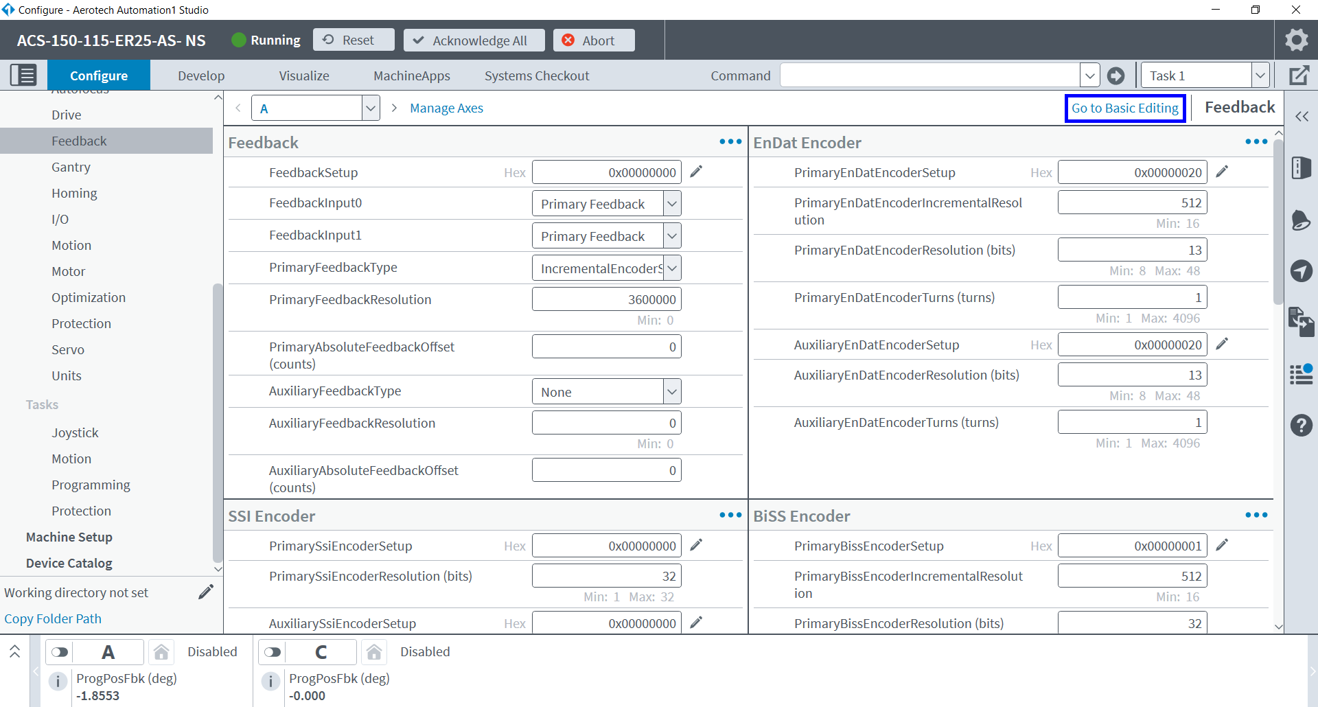
- Select the desired axis from the axis list.

- The axis will move automatically during the tuning process. Click View Motion Details to confirm the speed and distance which the axis will move.

- Click the Start button to perform automatic encoder tuning. The process will complete over the span of several seconds.

- You may examine the parameter changes by clicking Go to Advanced Editing if you wish.
- Click the Save All button under the parameter categories to commit the tuning change.
- The controller will reboot with the new encoder gains applied.
Follow these instructions if your stage can be Enabled without getting faults and can move short distances normally.
- Jog your axis to the center of travel using Motion Composer. Tuning should be started approximately at the center of travel, away from crash conditions.
- Run Digital Scope, and Connect to the controller.
- Navigate to the Feedback Tuning tab.
- Select the desired axis from the axis list and Enable
 the axis.
- Open the motion configuration box by clicking the drop-down arrow on the Tune
 button.
 - Select Enable Motion. The tuning utility will calculate an ideal distance and velocity for the tuning motion profile, which will be displayed in the Motion Configuration box. You can modify these values if you want to travel over a different range on the stage.

- Click the Tune button to enable the tuning motion and start the tuning algorithm. The tuning algorithm will continuously collect data and adjust the feedback gains so that the feedback device Lissajous matches the ideal Lissajous (red circle).
- Once the feedback device Lissajous matches the ideal Lissajous, click Stop
 to stop the tuning cycle.
 Once the feedback device gains have been calculated, we recommend that you check the Lissajous pattern over the entire length of travel of the axis. Check the pattern by moving the axis over the entire length of travel while displaying the Lissajous pattern. To only display the Lissajous pattern without tuning the axis, select the Collect Data
 button. Set a different motion profile using the drop-down arrow if needed.
Note
Alternatively, you can uncheck Enable Motion in the Motion Configuration window, select Collect Data, and jog the stage manually over the full travel using A3200 Motion Composer.
- If at some position the Lissajous becomes much larger than the ideal Lissajous, repeat the tuning procedure with the axis located at this position, then verify over the full travel again. Stop the data collection when you are done.
- The feedback gains that are calculated by the tuning algorithm are set as active on the controller but are not committed to the file system. To commit the parameters to the file system for future use, select the Commit Parameters
 button.
Follow these instructions if your stage can be Enabled without getting faults and can move short distances normally.
- Jog your axis to the center of travel using Motion Composer. Tuning should be started approximately at the center of travel, away from crash conditions.
- Run Digital Scope, and Connect to the controller.
- Navigate to the Feedback Tuning tab.
- Select the desired controller/axis and Enable the axis.

- Open the motion configuration box by clicking the drop-down arrow on the Tune button.
- Select Enable Motion. The tuning utility will calculate an ideal distance and velocity for the tuning motion profile, which will be displayed in the Motion Configuration box. You can modify these values if you want to travel over a different range on the stage.

- Click the Tune button to enable the tuning motion and start the tuning algorithm. The tuning algorithm will continuously collect data and adjust the feedback gains so that the feedback device Lissajous matches the ideal Lissajous (red circle).
- Once the feedback device Lissajous matches the ideal Lissajous, click Stop to stop the tuning cycle.
Once the feedback device gains have been calculated, we recommend that you check the Lissajous pattern over the entire length of travel of the axis. Check the pattern by moving the axis over the entire length of travel while displaying the Lissajous pattern. To only display the Lissajous pattern without tuning the axis, select the Collect Data
button. Set a different motion profile using the drop-down arrow if needed.
Note
Alternatively, you can uncheck Enable Motion in the Motion Configuration window, select Collect Data, and jog the stage manually over the full travel using A3200 Motion Composer.
- If at some position the Lissajous becomes much larger than the ideal Lissajous, repeat the tuning procedure with the axis located at this position, then verify over the full travel again. Stop the data collection when you are done.
- The feedback gains that are calculated by the tuning algorithm are set as active on the controller but are not committed to the file system. To commit the parameters to the file system for future use, select the Commit Parameters button.

In the event that you cannot Enable your axis for any reason, please use the below instructions to complete the encoder tuning process.
Follow these instructions if your stage receives any faults when Enabled, or if the axis is unstable. This process will require two people: one to operate the software, and one to move the stage manually/by hand (called the stage operator below).
Note
This procedure can only be completed on stages that can be moved safely and freely by hand while Disabled.
- Run Automation1 Studio and connect to the controller.
- Have the stage operator physically slide your axis to the center of travel Tuning should be started approximately at the center of travel, away from crash conditions.
- Navigate to the Configure tab, Axes > Feedback category.
- If you are in the Advanced editing view, click Go to Basic Editing in the top right corner.
- Navigate to the Manual Encoder Tuning tab at the bottom of the page.
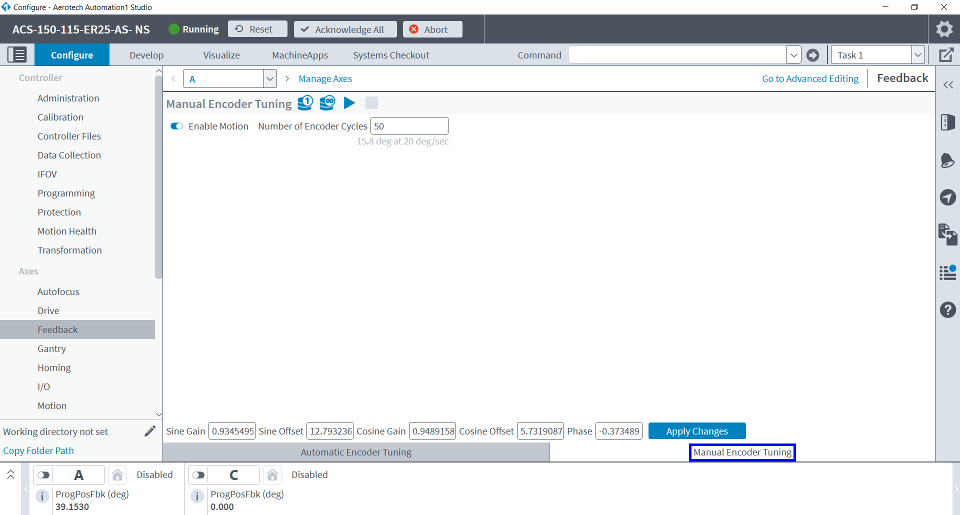
- Uncheck the Enable Motion toggle.

- Have the stage operator oscillate the stage in a small range of motion at an even rate. This simulates the function of the Enable Motion feature.
- Click the Tune Encoder Parameters
 button to begin tuning.
 - The software will automatically calculate a corrected set of encoder parameters, shown by the red Lissajous below. The red Lissajous data is overlapping the ideal 1 Vpp circle, displayed in black. This may not always be visible; it is marked by the blue arro16pxws in the below screenshot. The stage operator may stop oscillating the stage now.
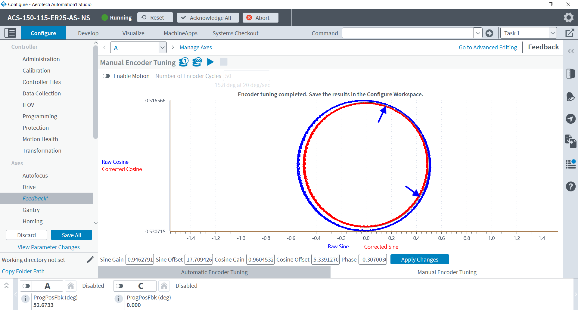
- Click the Apply Changes button.
- Click the Save All button under the parameter categories to commit the tuning change.
- The controller will reboot with the new encoder gains applied.
- You'll be placed back on the Manual Encoder Tuning page where we will now confirm that the encoder gains are acceptable across the full range of travel.
- Have the stage operator move the stage back and forth across the entire range of travel, at a slow and even pace.
- Click the Collect Continuous
 button to get the raw & corrected encoder data across the full range of travel. This will not modify the encoder gains.
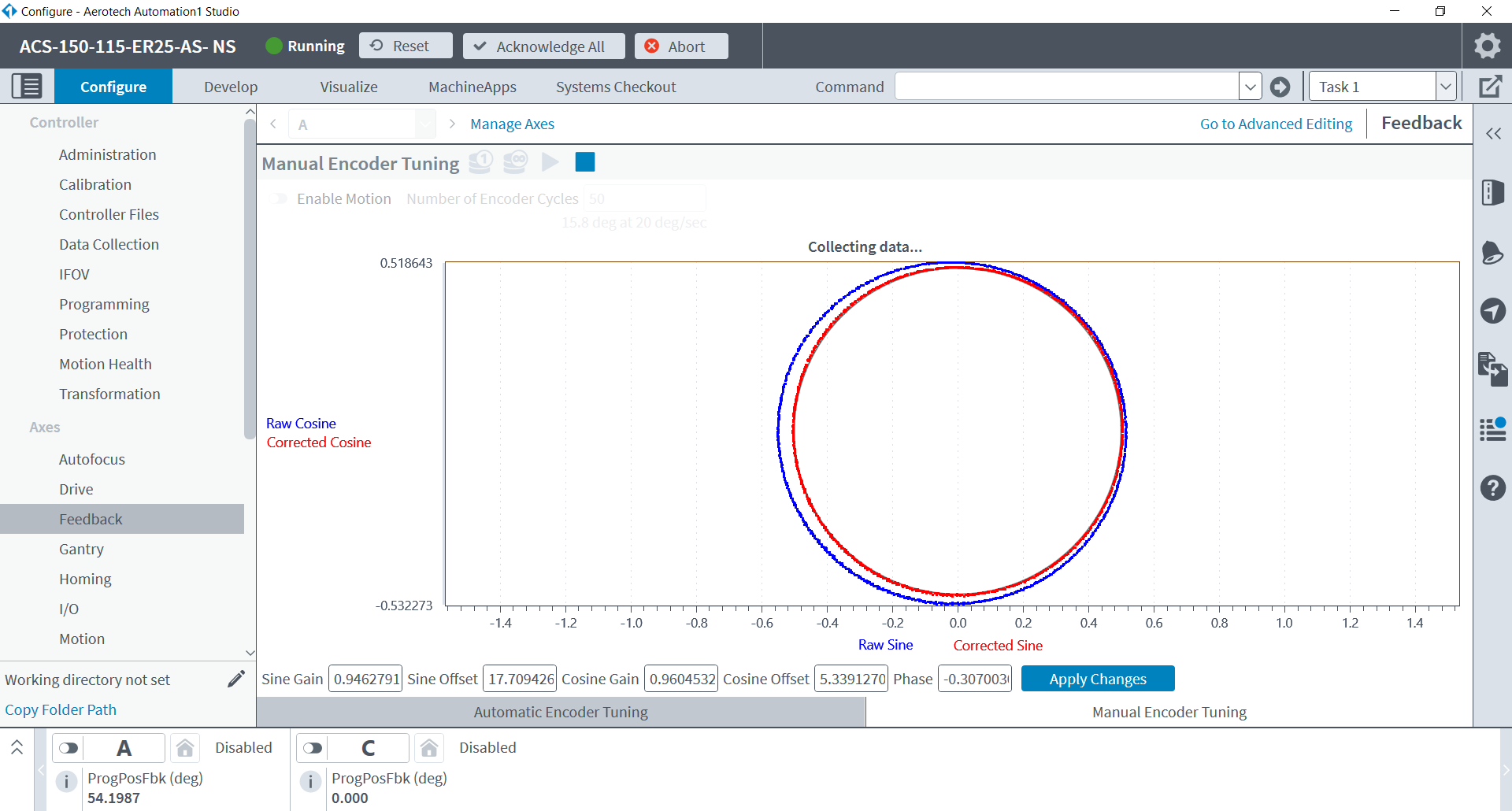
- The data will continually update as the stage operator moves the stage. Observe the data over the full range of travel.
- The corrected red Lissajous should remain on or somewhat inside the black 1Vpp circle. If at some position the Lissajous becomes much larger than the black circle, repeat the tuning procedure from the earlier steps with the axis located at that position, then verify over the full range of travel again.
- When you are satisfied that the encoder performance is adequate press the Stop Collection
 button and you may resume stage operation.
Follow these instructions if your stage receives any faults when Enabled, or if the axis is unstable. This process will require two people: one to operate the software, and one to move the stage manually/by hand (called the stage operator below).
Note
This procedure can only be completed on stages that can be moved safely and freely by hand while Disabled.
- Run Digital Scope, and Connect to the controller.
- Navigate to the Feedback Tuning tab.
- Select the desired axis from the axis list and Disable the axis. Acknowledge any faults that are occurring.

- Have the stage operator move your stage to the center of travel.
- Open the motion configuration box by clicking the drop-down arrow on the Tune button.
- Uncheck Enable Motion.

- Have the stage operator oscillate the stage in a small range of motion at an even rate. This simulates the function of the Enable Motion feature.
- Click the Tune button to start the tuning algorithm. The tuning algorithm will continuously collect data and adjust the feedback gains so that the feedback device Lissajous matches the ideal Lissajous (red circle).
- Once the feedback device Lissajous matches the ideal Lissajous, click Stop to stop the tuning cycle. The stage operator may stop oscillating the stage as well.
Once the feedback device gains have been calculated, we recommend that you check the Lissajous pattern over the entire length of travel of the axis. Check the pattern by having the stage operator move the axis at an even rate over the entire length of travel while displaying the Lissajous pattern. To only display the Lissajous pattern without tuning the axis, select the Collect Data
button.
- If at some position the Lissajous becomes much larger than the ideal Lissajous, repeat the tuning procedure with the axis located at this position, then verify over the full travel again. Stop the data collection when you are done.
- The feedback gains that are calculated by the tuning algorithm are set as active on the controller. but are not committed to the file system. To commit the parameters to the file system for future use, select the Commit Parameters button.

Follow these instructions if your stage receives any faults when Enabled, or if the axis is unstable. This process will require two people: one to operate the software, and one to move the stage manually/by hand (called the stage operator below).
Note
This procedure can only be completed on stages that can be moved safely and freely by hand while Disabled.
- Run Digital Scope, and Connect to the controller.
- Navigate to the Feedback Tuning tab.
- Select the desired controller/axis and Disable the axis. Acknowledge any faults that are occurring.

- Have the stage operator move your stage to the center of travel.
- Open the motion configuration box by clicking the drop-down arrow on the Tune button.
- Uncheck Enable Motion.

- Have the stage operator oscillate the stage in a small range of motion at an even rate. This simulates the function of the Enable Motion feature.
- Click the Tune button to start the tuning algorithm. The tuning algorithm will continuously collect data and adjust the feedback gains so that the feedback device Lissajous matches the ideal Lissajous (red circle).
- Once the feedback device Lissajous matches the ideal Lissajous, click Stop to stop the tuning cycle. The stage operator may stop oscillating the stage as well.
Once the feedback device gains have been calculated, we recommend that you check the Lissajous pattern over the entire length of travel of the axis. Check the pattern by having the stage operator move the axis at an even rate over the entire length of travel while displaying the Lissajous pattern. To only display the Lissajous pattern without tuning the axis, select the Collect Data
button.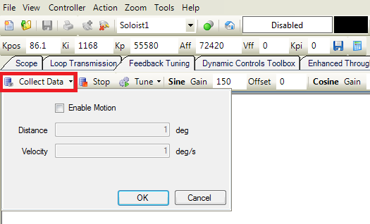
- If at some position the Lissajous becomes much larger than the ideal Lissajous, repeat the tuning procedure with the axis located at this position, then verify over the full travel again. Stop the data collection when you are done.
- The feedback gains that are calculated by the tuning algorithm are set as active on the controller, but are not committed to the file system. To commit the parameters to the file system for future use, select the Commit Parameters button.

Related articles